By Manny Arceo and Jack Haller
As fluid automation users embrace the advantages of new devices that draw unprecedentedly low levels of power, a few users are experiencing application issues that don’t
occur with older, higher-power-consumption equipment. These issues center around
supervisory and leakage currents generated by input/output (I/O) control systems. Such
currents can cause problems when interacting with new low-power components such as
solenoid valves and sensors.
This paper will review concerns that can arise when applying low-power and electronically enhanced solenoid valves within certain control systems. It will outline the limited
set of cases where problems can exist, and explain how to identify such cases. Finally, it
will provide tips and suggestions for possible workarounds or solutions that users might
consider after consulting I/O system manufacturers or their manuals.
In process plants worldwide, low-power solenoid valves are used as pilot valves to open
and close larger ball or butterfly valves, or on control valves for fail-safe air release if there’s
a loss of power or air. They work by pressurizing or depressurizing associated actuators.
The newest generation of low-power valves, such as the comprehensive line from ASCO
Numatics, draws only about 0.5 W, as opposed to the previous low-power standard
around 1.5 W. Such valves thus offer greater efficiency and energy conservation, and
accommodate the power consumption limits imposed by bus networks, backup power
schemes, use in remote locations, and so on. These advantages have been enthusiastically welcomed by original equipment manufacturers (OEMs) and valve assemblers, as
well as by end-users — anyone who specifies solenoid valves for refining, upstream oil
and gas, chemicals, pharmaceuticals and life sciences, food and beverage, and power
and steam.
However, users should be aware that recent advances in low-power solenoid valve design
are not always matched by necessary changes in I/O technology. A mismatch between the
control system and the valve can in some cases bring unintended consequences.
Where problems do arise, they can cause the valve to “hang” or stay open when desired
to close, so that process media may continue to flow. Depending upon your application,
this can impact costs, operational efficiency, and sometimes process reliability.

Most users who purchase and utilize relay-type output controls to operate solenoid valves
need not worry: their equipment will not be affected by these problems.
However, for applications where the solenoid valve assembly is managed by solid-state I/O
modules, some — though not all — users may encounter the problems described here.
Specifiers should match these new valves with the right new I/O modules (or consider
other steps, as outlined below) to obtain reliable operation.
When problems arise, they are due to the presence of two kinds of electrical current:
supervisory current or leakage current.
Supervisory current is a low-level loop current found on some traditional PLC/DCS output
modules. It’s part of a diagnostic scheme that module manufacturers devised to verify the
presence of open circuits.
The principle is that as long as a load is connected to the module, there should be current
flow. Only when the load is disconnected — creating an open circuit — should there be
zero current draw. So even in the “off” state, these output modules still keep a small
amount of current flowing.
Encountered slightly more commonly than supervisory current is leakage current. This is
not part of any diagnostic scheme, but rather unintended, residual current produced in a
module’s “off” state.
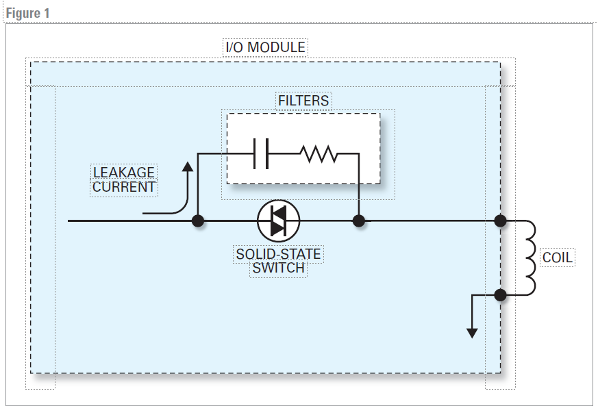
Ideally, an “off” condition should produce zero flow. However, in some I/O modules, electrical filters — used to protect against power surges and/or transient voltage spikes
caused by inductive loads — leak a small amount of output current. Also, in some cases
the off-state impedance of some solid-state switching devices is low enough to allow
current to flow. (See Figure 1 below.)
Leakage current is mostly present in solid-state AC applications using triacs. It can also
be found in DC I/O modules.
Again, the main type of valve possibly impacted by an output module mismatch is the
low-power solenoid valve.
A low-power coil operates at a much lower current than a standard solenoid valve. (It
thus de-energizes at a lower current also, termed the drop-out current.) In some cases, a
valve with an extremely efficient magnetic design can operate with only a few milliamps
of current.
Unfortunately, some existing I/O modules were designed when solenoid valves might
draw as much as 6 to 10 W, and not less than 1.4 W. At the time, any leakage or supervisory current the module emitted was below these levels to ensure the solenoid valve was
maintained in the “off” state, keeping it de-energized.
However, the new generation of solenoid valves draws only about 0.5 W. So some output
modules may generate a high enough leakage or supervisory current to inadvertently
affect valve operation.
Besides low-power valves, two recent types of electronically enhanced solenoid valves
can also encounter these problems.
A few models include options with a charging circuit that stores energy on capacitors.
Typically, an I/O module designed with problematic supervisory or leakage current produces enough flow to charge up these capacitors, keeping the valve in an undesired
energized (open) state.
Another electronically enhanced solenoid valve option found on a few models involves
peak and hold pulse-width-modulation (PWM) circuits. This type of power management
circuit provides a higher value of inrush current to energize the valve, then reduces the
power to hold the valve in the open position. Thus power to the valve is switched on and
off at a fast pace (i.e., at a high frequency). The longer the valve is switched “on” compared to its “off” time, the higher the power the valve consumes.
Users who specify a PWM circuit usually do so because it offers a lower holding mode,
reducing power consumption and heat rise in the coil. However, because the holding
power levels are lower than the power levels of standard solenoid valves, supervisory and
leakage currents beyond a specified value can prevent the valve from closing properly.
In some cases, supervisory or leakage current can be present without impacting solenoid valve operation. How do you know whether your valve is affected or unaffected?
One simple field test can provide an initial indication for most affected applications. With a
normally closed (NC) valve, the problem will manifest when the solenoid sticks in the open
position, even though the output module is turned “off.” The user can then try tapping the
valve lightly, or slightly lifting the solenoid. This helps overcome the magnetic force generated by a supervisory/leakage current, releasing the valve core and returning the valve to
its closed state. So if a simple tap or lift allows the valve to shift, a current problem
probably exists.
For confirmation or for a more definitive initial test, employ an amp meter or current
probe. With the I/O module in the “off” state, check for current output. If current is
detected, it’s a supervisory/leakage current situation. For modules that “pulse” current,
an oscilloscope will be needed to perform this evaluation.
In cases where current is discovered, the next step is to determine the drop-out current
of your particular valve. This is the current level at which the valve shifts back to its
closed state.
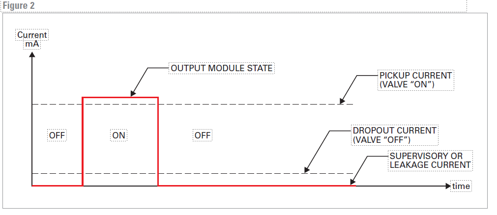
1. If the supervisory/leakage current is less than the drop-out current, the valve’s operation will not be affected. (See Figure 2.) No further action is necessary.
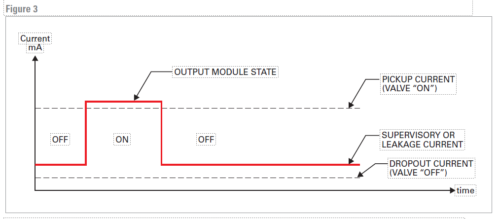
2. However, if the supervisory/leakage current is greater than the drop-out current, the
valve will seem stuck in the open position when de-energized. (See Figure 3.) You should
then consider the workarounds or solutions below
Users affected by I/O system/valve mismatches with supervisory or leakage current
problems have often found the following courses of action helpful.
Of course, applications differ, and this paper can’t address every user’s unique setup,
process, and equipment. Please consult your control module manufacturer and/or your
plant control engineer for definitive answers
For supervisory current, try switching software to passive mode
Digital output modules that utilize supervisory current often provide mode settings. In
active mode, supervisory current flows constantly throughout each output module.
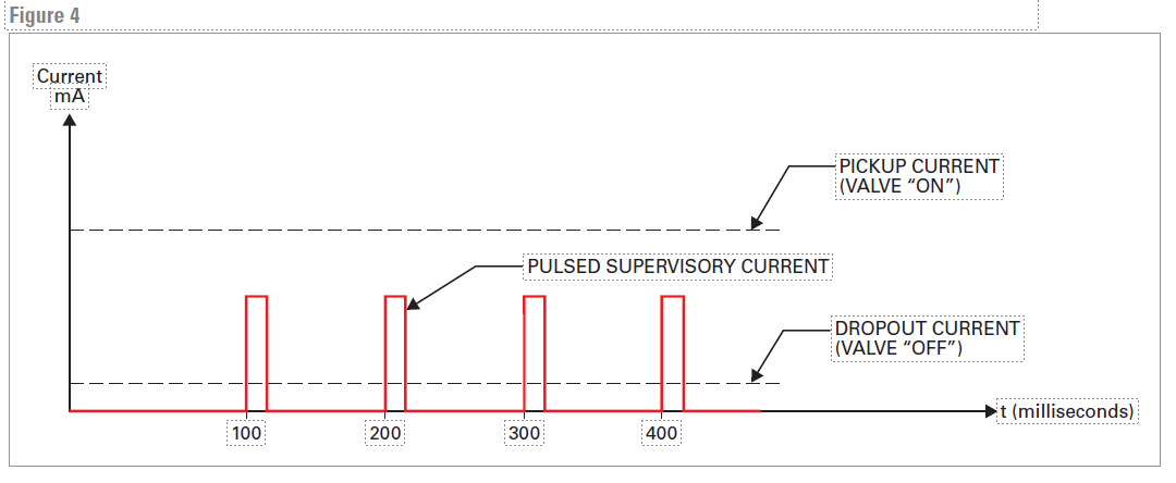
However, should active mode prohibit proper component operation, these module’s software lets users switch to passive mode. Here current is usually pulsed rather than continually applied. (See Figure 4). In this pulsed mode, the “on” time is significantly shorter
than “off” time, so valve operation is not affected, and this open-circuit diagnostic can
occur 100% of the time. Furthermore, the magnitude of the “on” pulse is lower than the
pick-up current. Result: despite the presence of supervisory current, the solenoid valve
will not turn “on” inappropriately.
Other I/O modules provide software configured in a different but also helpful way. Here,
passive-mode supervisory current only occurs once the valve has been cycled “on/off.”
In this mode, the I/O module checks for open circuits only when the output is in the “on”
state. Result: again, the valve will not turn “on” inappropriately.
For leakage current, try applying a loading resistor
Unlike supervisory current, leakage current cannot be handled by software settings.
Primarily caused by electrical filters built into the I/O module to guard against electrical
anomalies, leakage current is present 100% of the time in the “off” state.
However, manufacturers of PLCs and DCSs often include application notes recommending that concerned users add a loading resistor. With a particular resistance and
wattage in parallel with the valve, the resistor absorbs the excess current, and ensures that the current across the valve is below the drop-out current in the “off” state. This
eliminates or limits problematical leakage current effects. Adding a resistor is by far the
simplest solution, especially if the output modules are located in a marshalling cabinet
inside the control room.
Resistor value and wattage vary by manufacturer, depending on the magnitude and voltage of leakage. Area classification (Class I, Division 1 or 2) also affects what the user can
do to limit leakage current effects. Consult your control module literature or ask your
manufacturer to make sure a resistor is appropriate for your application.
New or upgraded installations
For supervisory current, select the right I/O module
When expanding or upgrading your control system, choosing the proper output module
can be the key to trouble-free, low-maintenance operation.
If you need supervisory current as part of your diagnostic scheme for detecting open circuit conditions, then:
• Consult the manufacturer for the drop-out current of the low-power solenoid valves you
intend to use.
• Select an up-to-date output module whose supervisory current is lower than your
valves’ drop-out current.
• If valves are the last components selected, first choose a compatible, modern output
module design, equipped with both active and passive modes for detecting open circuits. After installation, keep your module in passive mode.
• Ideally, select a module where supervisory current is “pulsed,” and present 100% of the
time. This provides 24/7 detection. And again, it generally won’t affect valve operation
(won’t prevent valve from inappropriately de-energizing).
New or upgraded installations
For leakage current, select the right module, apply a resistor, or try surge suppression
If you don’t need supervisory current, then:
• Consult the I/O module manufacturer’s data sheet to ascertain whether a given module
exhibits leakage current, and at what strength.
• Consult the valve manufacturer to learn the drop-out current for the valve you intend
to use.
• If the leakage current is less than the drop-out, valve operation will not be
compromised.
• If the leakage current is greater than the drop-out, connect a recommended loading
resistor to the valve. (See resistor discussion above.) Again, consult your control module literature or ask your manufacturer to make sure a resistor is suitable in your case.
• For another option, consider using the surge suppression version of a low-power coil.
Surge suppression coils that are not polarity-sensitive contain diodes in series with the
coil windings. In some cases, the added power drop across the diodes can be enough
to prevent the leakage current from keeping the valve energized.
New or upgraded installations
For leakage current, adjust your expectations about coil wattage
Finally, choosing an appropriate coil wattage can also ensure proper valve operation
with your selected I/O module, regardless of manufacturer.
Once your output module has been chosen and the magnitude of any leakage current
verified, simply select valves whose coil drop-out current is greater than that leakage
current. Advantage: resistors or surge suppressors become unnecessary — a preferred
outcome especially for remote upgrades, where adding components after initial installation could take a time-consuming, expensive maintenance trip.
Of course, leakage currents that are sufficiently high effectively rule out the use of the
newest low-power valves, depriving you of their power savings opportunities. If you face
this situation, instead of models drawing 0.5 W, consider higher-power valves.
Users’ demands for lower operating costs and increased product efficiency led directly
to the low-power revolution in valves and sensors. For example, as the world’s leading
solenoid valve manufacturer, ASCO has developed innovative technologies enabling the
production of solenoid valves that operate around the desirable 0.5 W mark.
Manufacturers of I/O technology are also responding to this trend. They’re introducing
I/O output cards with either pulsed or lower-current off-state supervisory systems.
Result: problem-free matches with the latest low-power valves.
Developing even more of these products for customers who could use low-power savings will be a win for both the I/O system suppliers and their customers. Lower power
consumption per valve would allow more I/O points to be designed into an I/O card,
reducing system installation costs.
The newest generation of low-power and electronically enhanced solenoid valves
provides attractive efficiencies and savings in energy use, installation, and equipment
costs. They have been enthusiastically embraced by OEMs and end users industrywide.
However, in some cases, these valves can be mismatched with I/O control module
systems that produce problematic supervisory or leakage currents. A number of
workarounds and solutions exist; optimal examples include new designs for the I/O
modules themselves that accommodate these valves. Users who pair a new low-power
valve with a newly designed I/O module will enjoy the best possible performance
going forward.
Copyright © 2024 Butler & Land Technologies, LLC. All Rights Reserved.
Web Design by Red Spot Design. Return & Refund Policy, Terms & Conditions